

Thermodynamic Steam Trap
Home » Our Products » Steam Traps » Thermodynamic Steam Trap
- Our Products
Thermodynamic Steam Trap
- get in touch
Reach Out to Our Team Today for Customized Industrial Valve Assistance and Inquiries
At Valvomatic Industries, we value open communication and are always here to assist with any questions or inquiries you may have. Whether you’re looking for more information about our products, need technical support, or have specific requirements for your project, our dedicated team is ready to help.
- our products
download brochure
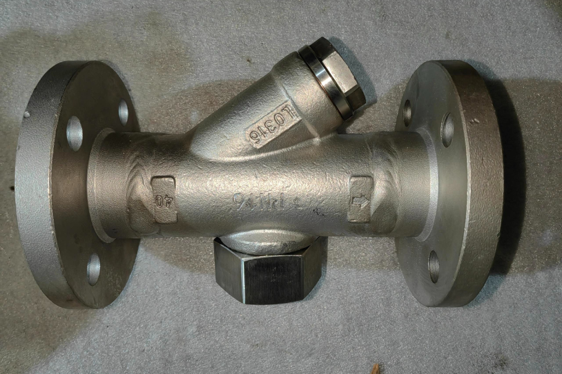
Thermodynamic steam traps are a type of mechanical steam trap that utilizes the thermodynamic properties of steam and condensate to automatically remove condensate from a steam system while preventing the loss of live steam. They are characterized by their simple design, typically consisting of a hardened stainless steel disc that opens and closes against a valve seat. This disc is the key component, responding to pressure and temperature changes within the trap. They are widely used in various industrial applications due to their robustness, compact size, and ability to handle high pressures and temperatures.
The operation of a thermodynamic trap relies on the difference in velocity and pressure between steam and condensate. When condensate enters the trap, it flashes into steam, creating a high-velocity jet that lifts the disc off the valve seat, discharging the condensate. As the steam and condensate mixture expands and cools, the pressure drops, and the disc snaps shut. The cycle repeats continuously, automatically removing condensate and air while preventing steam loss. This efficient operation makes them a popular choice in applications requiring reliable and economical condensate management.
Features of Thermodynamic Steam Trap
- Simple Design
- Compact Size
- High Temperature Capability
- Resistant to Waterhammer
- Fast Response to Load Changes
- Discharge Characteristics
Applications of Thermodynamic Steam Trap
- Heat Exchangers
- Kettle Boilers and Steam Generators
- Steam Distribution in Buildings
- Industrial Processes
- Power Generation
- Laundry and Dry Cleaning Facilities
Specifications of Thermodynamic Steam Trap
| Trap Type | Thermodynamic |
| Manufacturer | Volumetric (Hypothetical) |
| Body Material | Stainless Steel (e.g., 304, 316) |
| Disc Material | Stainless Steel (Hardened) |
| Valve Seat Material | Stainless Steel |
| Connection Type | Threaded (NPT, BSP), Flanged (ANSI, DIN), Welded |
| Connection Size | [Specify sizes, e.g., 1/2", 3/4", 1", 1 1/4", 1 1/2", 2"] |
| Maximum Operating Pressure (MOP) | [Specify pressure, e.g., 600 psig (41 bar), 900 psig (62 bar), etc.] |
| Minimum Operating Pressure (MOP) | [Specify pressure, e.g., 3.0 psig (0.2 bar)] |
| Maximum Back Pressure | [Specify as a percentage of inlet pressure or in absolute units, e.g., 80% or 100 psig (6.9 bar) with 250 psig (17.2 bar) inlet pressure.] |
| Operating Temperature Range | [Specify the range, e.g., -20°C to 300°C (-4°F to 572°F)] |
| Capacity (Condensate Discharge) | [Specify capacity at different pressures. This is a critical specification. e.g., 1000 lbs/hr (454 kg/hr) at 100 psig (6.9 bar), 1500 lbs/hr (680 kg/hr) at 50 psig (3.4 bar)] |
| Length (Overall) | [Specify dimensions, e.g., 5 inches (127 mm)] |
| Height | [Specify dimensions, e.g., 3 inches (76 mm)] |
| Width | [Specify dimensions, e.g., 2 inches (51 mm)] |
| Weight | [Specify weight, e.g., 2.5 lbs (1.1 kg)] |
| Built-in Strainer | [Yes/No, or "Optional" if an option is available.] |
| Discharge Style | Intermittent/Continuous |
| Insulation Options | [Yes (specify type, e.g., jacket or "Available as an option", or No)] |
| Waterhammer Resistance | [Yes/No, or "Good," "Excellent" if it is designed to withstand the waterhammer.] |
| Compliance | [Specify applicable standards, e.g., ASME, PED (Pressure Equipment Directive), etc.] |
| Certifications | [Specify any relevant certifications, e.g., CE Marking] |